Qualitative Body-Powered Trikke Physics
Draft: 21 November 2022
Like the Trikke itself, three wheels spinning freely under 3 tubes joined by an ingenious camber joint, this article endeavors to capture the gestalt of Trikke locomotion. In the process, it gives Trikke Riders the knowledge to answer the greatest question a Trikke Rider ponders: Are you, the Rider, rotating the Trikke or is it rotating you?
Conservation and Parallel Axes
The primary role falls to The Law of Conservation of Angular Momentum, which holds the physics together. Secondarily, the Parallel Axis Theorem provides necessary expressions for moment of inertia, an easy exercise for the interested. Note that the Trikke's Turn-Radius must increase from its initial value to infinity and back again. Ramifications of this dynamic and many others including friction are not mentioned here. Those interested in such details please read the detailed article on "Body-Powered Trikke Physics" at http://www.lastufka.net/trikke/.
In broad strokes, I show here what happens according to Trikke Physics during the two phases of two half drive-cycles, making a complete cycle. While this high-level model shows the main workings of Trikke locomotion, it is completely qualitative. It's conclusions derived by applying The Law of Conservation of Angular Momentum only show that movement is possible and in what direction. It is not able to show that friction of any kind is overcome, or that the Rider is able to perform the necessary motions needed to drive the vehicle. For a quantitative computer model, see the article titled "Dynamic Model of a Trikke T78 Air" at http://www.lastufka.net/trikke/.
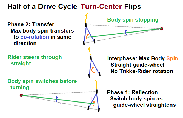
Phase 1 First Half Drive-Cycle
Initial Conditions
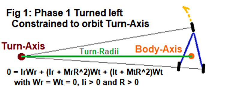
Figure 1 illustrates a Trikke steered left in a circle poised to travel counter-clockwise, because the wheels don't slip. Note two rotation axes: the Rider's vertical Body-Axis portrayed by an orange dot and the vertical Turn-Center axis or simply the Turn-Axis shown as a brown dot.
I use the word "spin" exclusively to indicate the Rider's spin about his own Body-Axis and "rotation" to indicate the Trikke and/or Rider's rotation around the Turn-Axis. Only the Rider spins around the Body-Axis, but both he and the Trikke rotate together (co-rotate) around the Turn-Axis along the path represented by the yellow arch. Importantly, the Rider typically spins around his Body-Axis and rotates around the Turn-Axis at the same time. This model keeps track of both motions independently.
Positive (+) spin and rotation occur counter-clockwise; the direction of the yellow arch. To understand the mathematics and results, one must keep track of the signs (+/-) of these rotation variables which switch in relation to the geometry due to the side of the Trikke the Turn-Center is on. That relationship dictates whether clockwise or counter-clockwise orientation becomes forward or backward motion.
At rest, the Rider is not spinning nor rotating. The Trikke is also at rest; not rotating.
Initial Actions
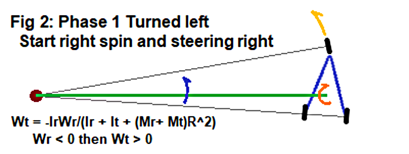
Optimally in Phase 1 of the first half drive-cycle, the Rider starts by spinning opposite (orange arch) the Trikke's counter-clockwise turn (yellow arch) illustrated in Figure 2. This co-rotates the Trikke and Rider counter-clockwise around the Turn-Axis as the Rider continues to spin up. Applying The Law of Conservation of Angular Momentum to this figure results in an equation that reflects the angular momentum of one term to the other. As the Rider spins up, so does the rotation around the Turn-Axis but in the opposite direction. When the Rider begins to steer the Trikke clockwise, it takes some time for the Guide-Wheel to straighten out. During this first phase of the half drive-cycle, while the Trikke steers less-and-less to the left and the Rider spins clockwise, the Trikke and Rider co-rotate forward, counter-clockwise.
Steering Almost Straight
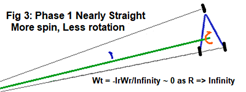
This initial motion is greatest right at the start, but as the Rider steers clockwise, the Guide-Wheel nears going straight as in Figure 3. While angular momentum reflection into the Trikke and Rider's rotation peaks, the rotation rate drops as the Turn-Radius increases to infinity. The closer to straight the Guide-Wheel turns, the less the Trikke-Rider co-rotation can be. When straight, the wheels all parallel, prevent it and it stops.
Interphase
Straight Ahead
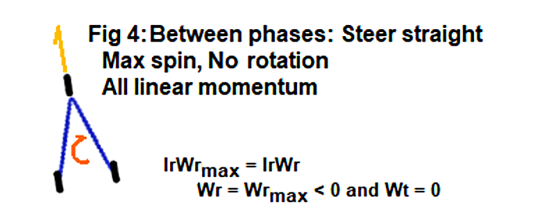
When turned straight as in Figure 4, whatever forward rotation Rider and Trikke achieved has been converted to forward linear momentum, because Trikkes have good bearings. See the article on Trikke Physics for the details of this conversion.
Phase 2 First Half Drive-Cycle
Steering Past Straight
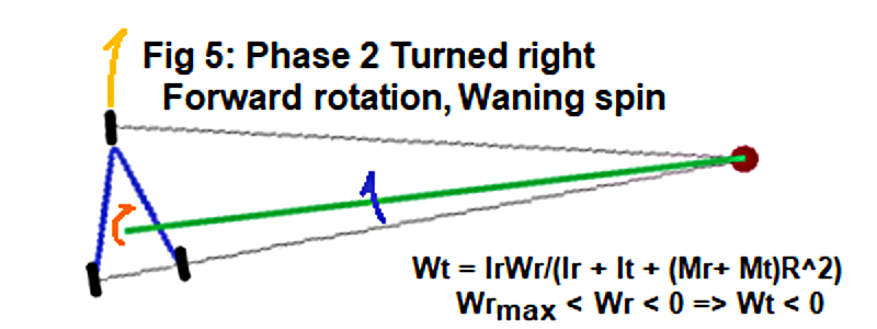
Steering clockwise past straight, the Rider relaxes decreasing spin as in Figure 5. Note the Turn-Center is on the right side now. This is the second phase of the first half drive-cycle. The Law of Conservation of Angular Momentum still applies but with different conditions. Initially there is only Rider Body-Axis spin, but at the end it is all transferred to Trikke-Rider rotation around the Turn-Axis. This is a transfer process; no longer reflection.
The Turn-Center flip also flipped the rotation sign, so the Trikke and Rider continue to move forward on a new arch.
Rider Spin Exhausted
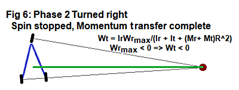
By the time the Rider stops spinning (Wr = 0) in Figure 6, all of his Body-Axis spin's angular momentum has been transferred to co-rotation around the Turn-Axis. Note that the Rider is now synergistically "wound up" for the spin to the other side!
Phase 1 Second Half Drive-Cycle
Spin Starts to Other Side
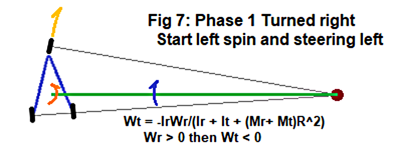
At this time, the rider begins to repeat the above process by spinning counter-clockwise as illustrated in Figure 7. This is phase 1 of the second half of the drive-cycle. The Rider also begins to turn to the other side, perhaps slightly delayed from the spin for more momentum reflection. This co-rotates the Trikke and Rider clockwise around the Turn-Axis as the Rider continues to spin up. This is all mediated by the Law of Conservation of Angular Momentum. When the Rider begins to steer the Trikke counter-clockwise, it takes some time for the Guide-Wheel to straighten out. During this first phase of the drive-cycle, while the Trikke steers right and Rider spins counter-clockwise, the Trikke and Rider co-rotate forward, clockwise, by angular momentum reflection.
Phase 2 Second Half Drive-Cycle
Steered Past Straight
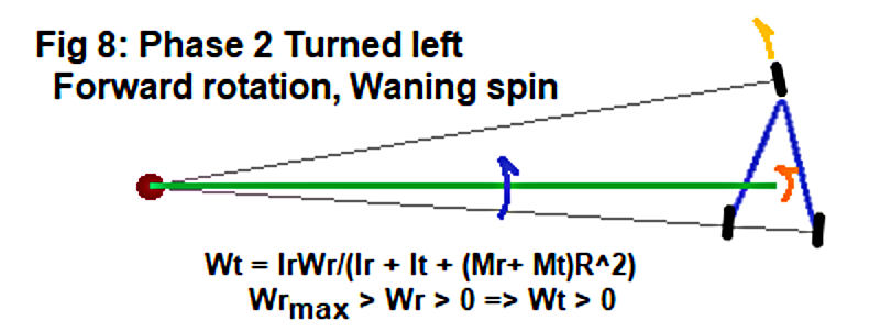
As in the previous half drive-cycle, passing straight means that the Rider has reached maximum spin. Steering counter-clockwise past straight, the Rider relaxes decreasing spin as in Figure 8. All of the Rider's angular momentum will be transferred into co-rotation when spinning stops. Note the Turn-Center is on the left side once again which changes the rotation sign so, the Trikke continues to move forward. This is phase 2 of the second half of the drive-cycle characterized by angular momentum transfer.
Phase 2 of the second half drive-cycle ends when the Rider stops spinning and all his angular momentum has been transferred to the Trikke-Rider co-rotation around the Turn-Axis. The Rider is wound up with Trikke steered, ready to begin another drive-cycle as in Figure 1.
Summary
Each drive-cycle, the Turn-Center flips twice; once each half-cycle. Phase 1 occurs before the flip followed by Phase 2 after the flip. The Rider spins in only one direction each half-cycle. This results in the reflection of his spin-up angular momentum during the first phase and transfer of his spin-down angular momentum during the second phase. Trikke design takes advantage of these synergies mediated by The Law of Conservation of Angular Momentum.
A 5-minute companion video "Trikke Co-rotation" demonstrates the reflection and transfer actions via a small experimental device on YouTube.
Conclusion
Modeling Trikke locomotion coarsely in this way shows that the Trikke-Rider system is an Alternating Rotation Transducer winding a path similar to a Kármán Vortex Street. The spin of the Rider around his Body-Axis is transferred via The Law of Conservation of Angular Momentum and the Parallel Axis Theorem to the Rider and Trikke orbiting the Turn-Axis as a single object. This is accomplished by a virtual armature, the Turn-Radius, that exists because Trikke wheels don't slip And flips sides as steering passes straight.
This simple qualitative model is also "local". It does not attempt to show that the motions connect to create the characteristic serpentine Trikke tracks. It does not explain how the incremental forward rotations accumulate momentum and speed. It does not demonstrate how the Rider produces spin. But for aspiring Riders and the experienced, it motivates us to figure out how to better "spin" our body mass independent of the Trikke's rotation.
Indeed, the most important result demonstrates two distinct types of Rider motion; 1) body spin and 2) rotation with the Trikke around the Turn-Axis. Knowing the difference helps each of us answer for ourselves the most important question of all for a Trikke Rider - Are you co-rotating the Trikke or is it rotating you? The more a rider co-rotates the Trikke, the faster it goes. When the Trikke rotates you, you are coasting. There's a time for that. Do it on purpose.
Spinning produces body angular momentum that reflects then transfers into co-rotation of the Trikke and Rider as the Rider spins up steered in the opposite direction and as he spins down steered in the same direction. A delay between the start of spinning and steering increases spin-up time to steering straight. This allows higher spin rates, thus body angular momentum, to be achieved for increased speed. Two "Trikke Magic" articles on the afore mentioned website, explore a few ways to create the spin to drive a Trikke.
References
Articles from http://www.lastufka.net/trikke/
[physics] Michael Lastufka, "Body-Powered Trikke Physics" June 2020.
[calibrated] Michael Lastufka, "Empirical 2nd Degree Friction Model Solution" June 2020.
[simulation] Michael Lastufka, "Dynamic Model of a Trikke T78 Air" June 2020.
[behaviors] Michael Lastufka, "Survey of Simulated Trikke Behaviors" June 2020.
[magic] Michael Lastufka, "Trikke Magic: Leveraging the Invisible" June 2020.
[Quick Start] Michael Lastufka, "Trikke Magic: Start Carving" June 2022.